Awesome, cheap, 10-ish watt HF transceiver with open-source software. Take a look at how I built mine.
Find the software here: ubitxv6, buy here and learn to wire it up here.
Useful 3D printed accessories
Case here. Microphone 1, 2. Raduino bracket here.
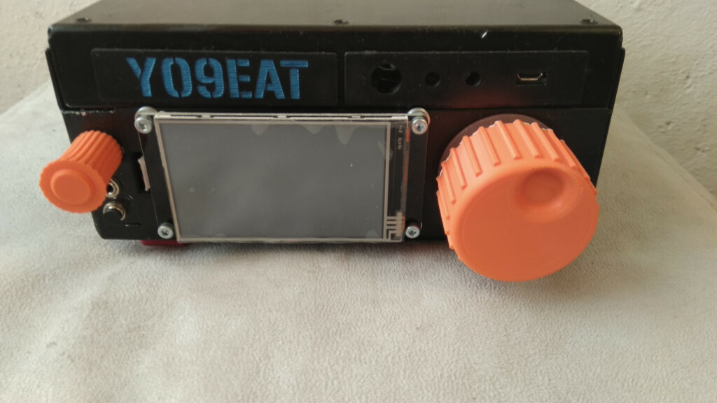
Front
The front plate only had metal edges, so I had to 3D print a panel for it (it slides into place onto the metal edges and stays in place quite well). The volume and VFO knob are 3D printed.
Left side has the microphone jack (I don’t see the reason for multi-pin microphone jacks, a simple audio jack does just fine) and the CW key jack with a blanking plug, as I don’t do CW. Yet.
The screen is the already famous Nextion 3.2 “smart”, code NX4024K032. Very fancy stuff for the price, albeit mine flexes a little when pressed (almost like it was meant to be a big button, might be a manufacturing problem or might need to press into place with a bezel, but I don’t care much about it honestly). I liked how it looked with screws only, so that’s how it stayed. Screen foil is still installed 😛
Top slots were also empty, so I designed and printed two blanking plates – one with the call sign, one with holes for leds and a switch (if needed) and the USB connector for CAT and audio.
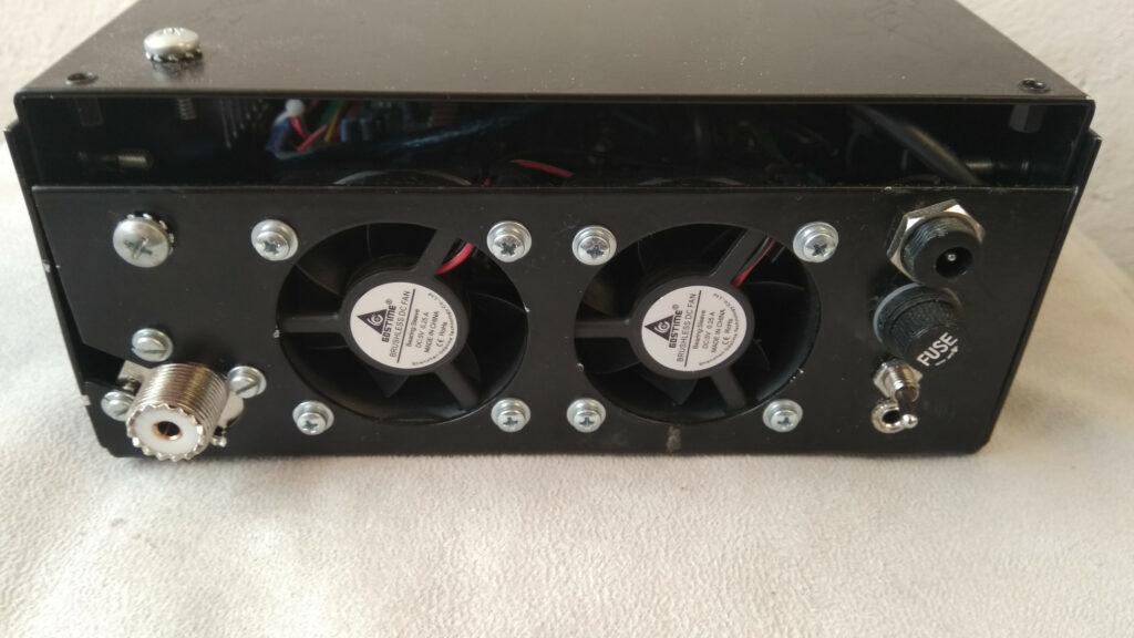
Rear
On the rear, two new fans installed in place of the old dirty ones (I know Ashar says they’re not needed, but I like cool electronics). They are manually toggled on/off using the switch on the right side of the panel, under the fuse holder.
SO-239 plug for the antenna, standard power jack, added fuse holder and headphone output jack. The screw on the left with star washers will be (sometime in the future) grounded to the lid screw for common ground.
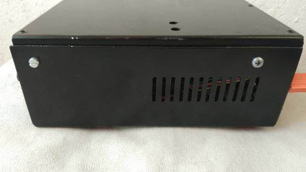
Sides
Boring. One day, I’ll maybe use identical screws for the front and rear!
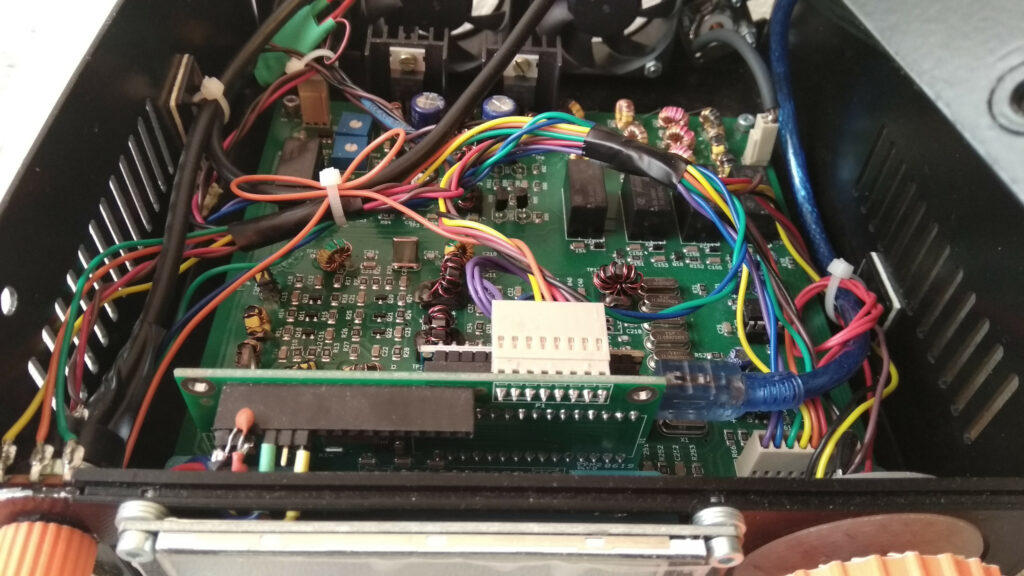
Top
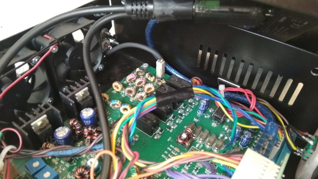
Some attempts at wiring management were briefly seen. Rear left of the LCD I added a small capacitor for the Nextion power. Blue USB cable goes to Raduino.
Corner top
Small glimpse of the Raduino bracket in the right of the picture (printed in blue). Black audio cables go to the USB sound card (top of the picture), where the jacks were so close I had to ground the cable coating in order to get them to fit.
Inside of lid
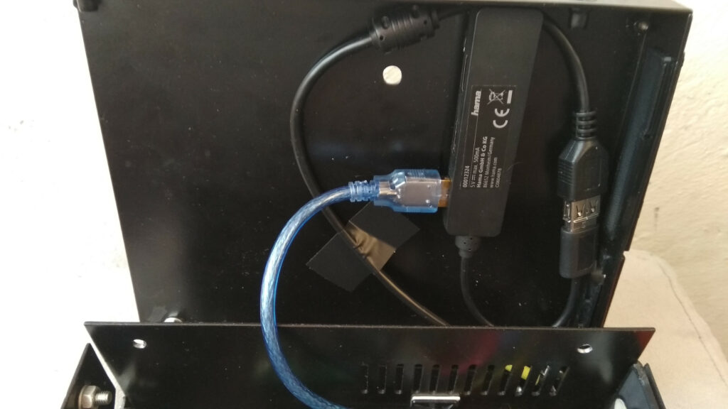
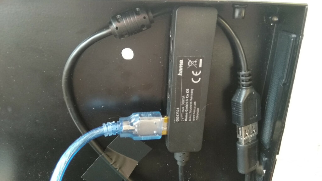
The only place I could find for the USB hub was on the lid, where it’s stuck with 3M Scotch Lock, excellent stuff. The hub is a cheap one from Hama and I’ll have to change it, because it only provides 500 mA total. For now, it’s working; however, if I put in a better sound card, the USB connection starts to drop – voodoo. At least it has a ferrite on the cord, haha.
Antenna connection
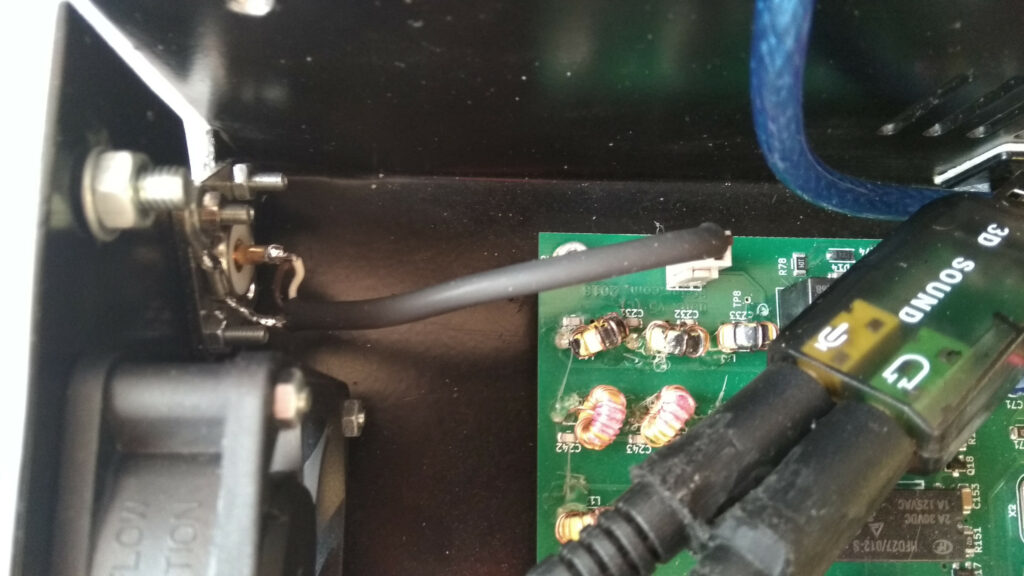
As I’ve said, SO-239 for lyfe bro. Replaced the standard cable with a shielded one by taking out the pins from the original connector and reconnecting them to the shielded cable. I know, crazy.
USB sound card and encoder
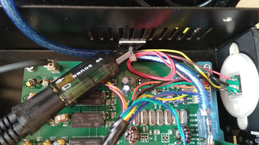
Cheap USB soundcard, does the job. Transparent backing plate for the encoder because it’ll one day have LEDs for that cool back glow. More attempts at cable management were seen.
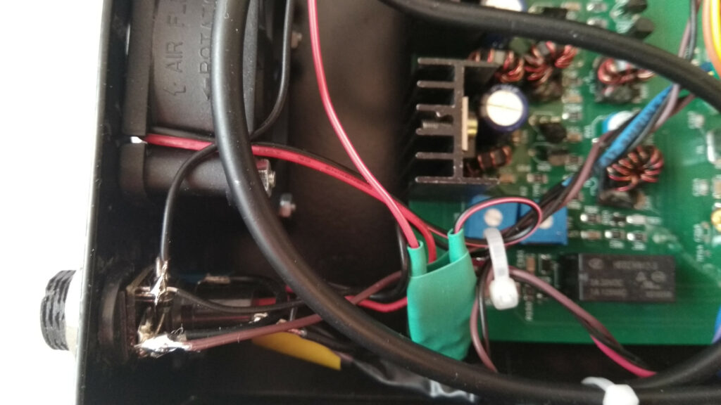
Fan connection
I wanted to devise a clever two way method to connect them, but got bored, so they’re connected in series. Two 5V fans and some resistors, bliss.
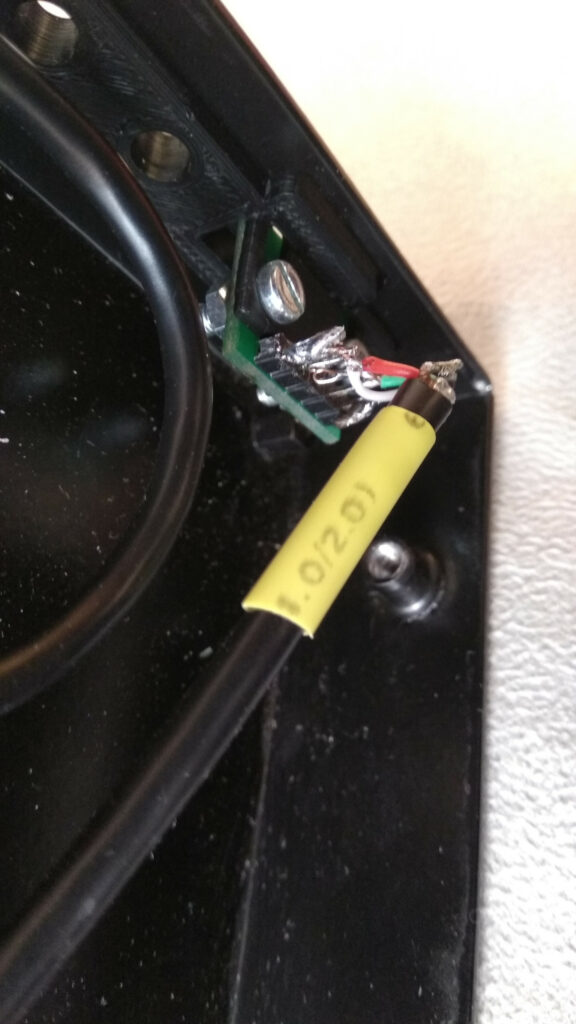
USB connection
This is again a 3D printed bracket to hold a micro-USB breakout board, to which the USB hub cable was cut and soldered. Albeit very ghetto looking, it works (yeah, I’m amazed as well). This allows me to have only one USB cable to the uBitx, carrying both CAT control and audio over USB. JUST LIKE THE FREAKING ICOM IC-7300, DUDE !
USB hub (again)
So, one cable from my PC to the uBitX, cable goes next to the USB hub, which in turns talks to the Raduino and does audio passthru using the USB sound card. Nifty. Notice the kapton tape on the + and – lines of the blue USB cable – this is done to avoid the USB hub powering the Raduino, which can turn bad. This way, the hub only does data and not power.
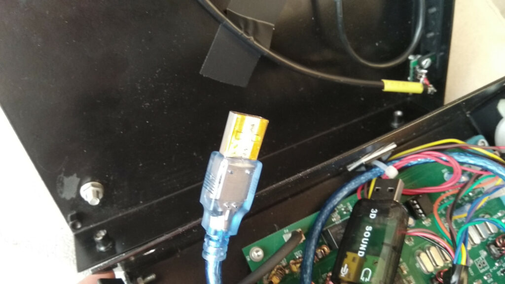
To be done
LEDs, S-meter, change USB hub, add mic compressor once I start doing SSB instead of digital modes.
Done
RTC clock face and battery installed.